

3d printed pan-tilt set for FPV optimized for ES Drifter Ultralight.:
XL-RCP 16.0 XYCLOPS : Cockpit camera pan-tilt for 808 #16.

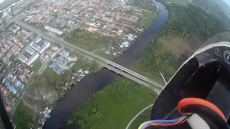
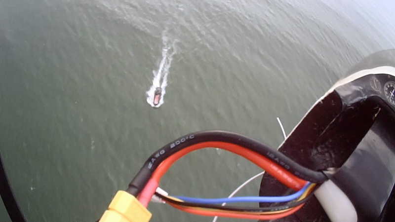
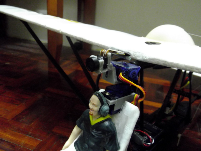 I designed this because it need to have extra camera tilting feature that able to view straight to ground while flying in cockpit view manner without adding extra weight and avoid looking too bulky. This kit is similar design to XL-RCP14.0 HAWX EYE but slightly beefy, rigid, heavy by few grams and high mounted behind the cockpit. HAWX EYE runs on 3.7g servos while XYCLOPS run on powerful 9g servos (optionally with 180deg after market servo) which is more commonly use by most FPV / drone flight enthusiast. The most prominent differences between them is the sizing and they way how the kit was mounted on the plane. XYCLOPS originally was designed for on ES Drifter Ultralight plane, it has seat mounted post and adapter to attached to the main pillar of wing structure for rigid placement and vibration damping purposes.
This kit reduce the weight of overall vs conventional pan-tilt system in the market yet able to utilized popular 9g size servo. This kit still retain its original purpose for cockpit flying experience with extra camera tilting feature. The narrow profile design starting from 808's lens all the way to the back allow more aerodynamic efficiency against the wind and reduce drag.

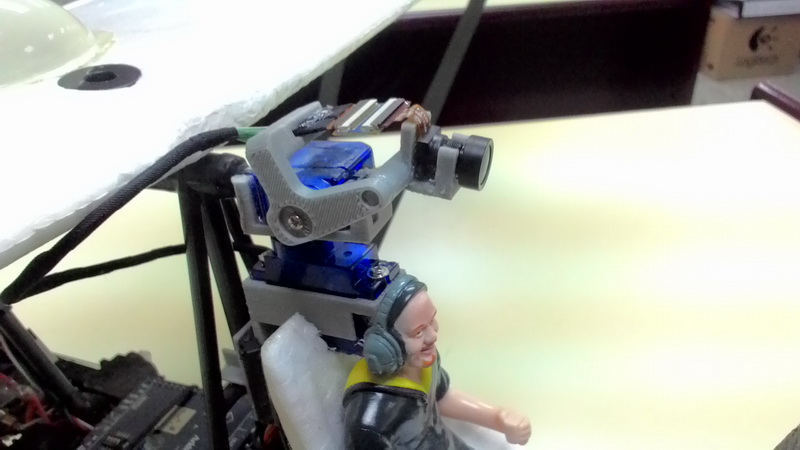
As usual like i said before on XL-RCP14 previous same documentation;  this kit is to be used with stripped "808 #16 V2 HD Key chain camera" with camera lens extension cable and 2x mini 9g servo connected to default available channel port on the receiver (eg: ch7 and ch6) via head tracking unit to sync
 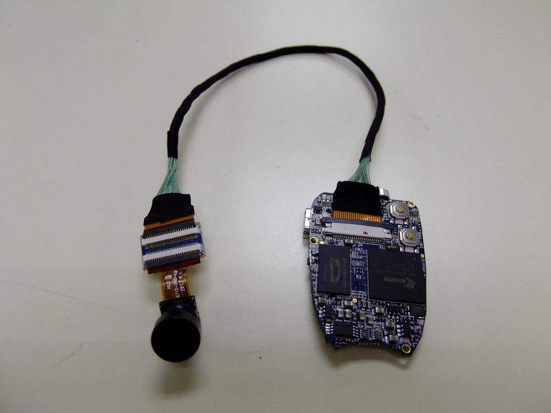 the pilot head movement with the set. Please check the parts list below the page for raw assembly unit.
This 3d printed kit consist of 5x parts: the "lens_socket.stl", "tilt_arm.stl", "tilt_servo_holder.stl", "pan_servo_base.stl" and "drifter_pillar_jig.stl". 6th optional parts the "808_mounting_board.stl" also included to mount the camera main board without original black case to trim the weight down. Required or recommended to be 3D print using plastic ABS material for rigid structure. Once done printing user only need to shed off support material and snap in all the required electronic hardware by hand. There need some servo screws needed to secure the servo pivot shaft and pan servo. Hot glue needed to snap and secure the tilt servo placement and also require to glue the "lens socket" to "tilt_arm" and "pan_servo_base" embedded into the surface of the plane either below the nose, inside the cockpit or where you preferred.
 |
 |
 |
 |
Specification & requirements:
- Camera: 808 #16 V2 keychain camera with 120 D-lens.
- Servo: 2x 9g micro servo. Dimensions (LxWxH): 21x12x22mm.
- Camera extension cable: Extension cable to extend the camera lens module away from 808 #16 board.
- Screws, super glue and hot glue needed for the installation procedure
Complete assembly parts:

Blow-out parts:

How to (On ES Drifter Ultralight installation):
- Install the "drifter_pillar_jig.stl" onto the first wing pillar just behind the ES Drifter Ultralight's seat. You will find a "+" structure to brace in the "drifter_pillar_jig.stl". It must be installed between the seat and the pillar not behind the pillar. Use hot glue to secure it to the pillar
 Then install the pan servo into "pan_servo_base" and screw it firmly into the screw tab. Then embedded into the top of your ES Drifter Ultralight epo foam seat. You'll need to trim the seat with pen knife to properly seat the base of 9g servo base width/thickness.
 - The "pan_servo_base.stl" have a flat wall surface which interface with the "drifter_pillar_jig.stl" via thick double sponge tape which you need to stick between them manually. Once all perfectly in place use hot glue to secure the top of the seat and the "pan_servo_base.stl"
- Then insert pan servo pivot shaft below the "tilt_servo_holder" socket and screw it in.
- Place tilt servo into "tilt_servo_holder" and secure it in place using hot glue.
- Then insert the "tilt_arm.stl" into the tilt servo pivot shaft and screw it firmly.
- Insert the "lens_socket.stl" into the tip of the of the "tilt_arm.stl" where the insertion hole located.
- Install the 808 #16 V2 camera lens module into the "lens socket.stl" socket joint. Carefully route the cable through the "tilt_arm.stl" cable holder for clean installation. Adjust the tilt angle of the "lens_socket" at your preferred angle before glue it permanently for tight installation at the socket joint.
- Route all your servo cable and lens cable clean and plug into your respective Radio Control receiver port and camera board.
- The "808_mouting_board.stl" is optional installation parts for your caseless style 808 camera pcb board.
Please refer to the gallery folder for images reference/manual once done download the zip file and extraction. Set your 3D printed to more denser printing material for robust and rigid product output.
![]() Gallery |
Gallery | ![]() Download STL file for 3D printing |
Download STL file for 3D printing | ![]() Download Development *.3DS kit only
Download Development *.3DS kit only
 Your shopping list to buy parts to build the above model (100% fit unless mentioned "Compatible"):):